Thursday 14 December 2017

LAB 06 - STATIC CORRECTIONS

MATLAB SCRIPT LAB 6.1

load SeismicData_gain_bpf_sdecon_gain_sorted_nmo_corrected_stacked_C.mat cmp_num t Dstacked

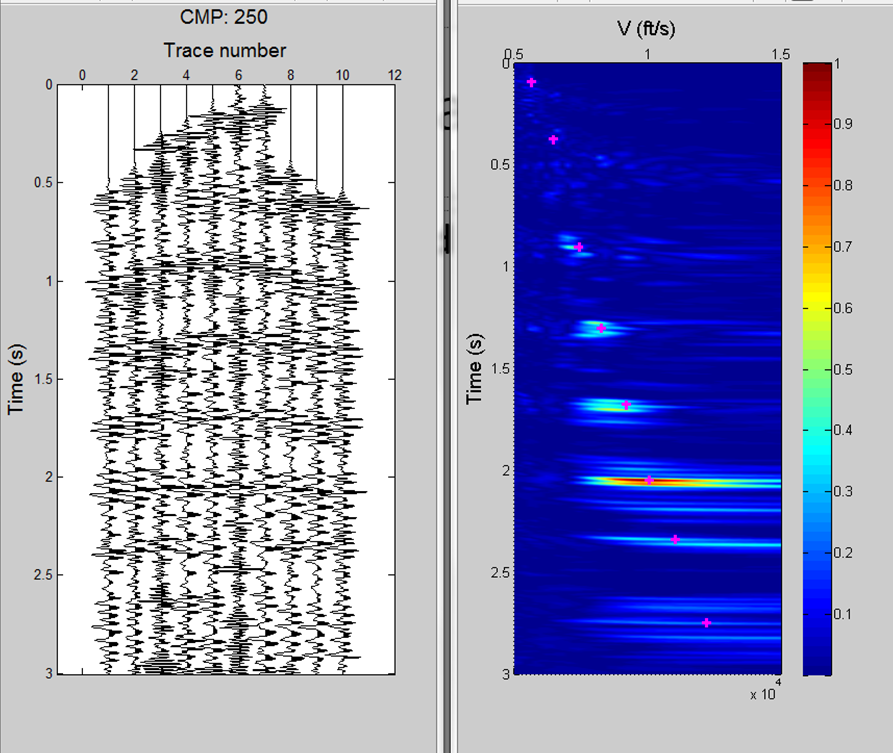
The following MATLAB script uses the M-function scr_static.m that implements the static correction steps and apply them to the CMP NMO corrected data, followed by stacking those statically corrected CMP gathers

%% Extracting CMP gathers
cmp_start=205;
cmp_end=205;
lags=20;
% Applying static correction
Dsort_static=scr_static(Dsort,Hsort,cmp_start,cmp_end,lags);
[Dstacked_static,t,cmp_num]=sstack(Dsort_static,Hsort);

%% Save static
save SeismicData_gain_bpf_sdecon_gain_sorted_nmo_corrected_static Dsort Dsort_static Hsort Dstacked_static cmp_num t

% Display Before Static Correction
scale=1;
figure(1);
simage_display(Dstacked,cmp_num,t,1)
xlabel(['CMP:',num2str(cmp_num),''],'FontSize',14)
ylabel('Time(s)','FontSize',14)
title ('Before Static Correction','FontSize',14)

Picture
Figure 1: ​Display Before Static Correction

% Display After Static Correction
scale=1;
figure(2);
simage_display(Dstacked_static,cmp_num,t,1)
xlabel(['CMP:',num2str(cmp_num),''],'FontSize',14)
ylabel('Time(s)','FontSize',14)
title ('After Static Correction','FontSize',14)

Picture
Figure 2: ​Display After Static Correction

Figure 3 below shows both the stacked data before and after applying the surface consistent residual static correction method. Clearly, the data quality has been improved after applying the correction where you will notice the extension of the continuity to many of the layers. 

Picture
Figure 3: Comparison display before and after static correction

LAB 05 - NMO CORRECTION & STACKING

MATLAB SCRIPT LAB 5.3 

clear all,close all,clc
load SeismicData_gain_bpf_sdecon_gain_sorted_C.mat
load SeismicData_gain_bpf_sdecon_gain_sorted_velocities_C.mat

%% Apply NMO correction
max_stretch=10;
[Dsort,Hsort]=nmo_correction(Dsort,Hsort,v_stack,t_stack,cmp_start,cmp_end,cmp_step);

Stacking NMO corrected and stretched traces will severely damage the shallow seismic events. Therefore, we have to remove the stretching before we stack. We do this by muting the considerably stretched zones from the gather. The muted zone is usually set to threshold with typical value between 0.5 to 1.5. Selecting a small threshold value avoids stretching but might cause excessive loss of data while selecting large threshold value avoid loss of data but might introduce excessive stretching of the data. You can notice that the hyperbolic seismic events have become more flat for different layers (try to see the results from CMP number 220, 230 and 250). Now, you are ready to obtain the first approximation of the subsurface image using stacking.

%% Save NMO correction
save SeismicData_gain_bpf_sdecon_gain_sorted_nmo_corrected_C.mat Dsort,Hsort

The purpose of stacking is to enhance SNR ratio by eliminating coherent and incoherent noise and to reveal a first subsurface image approximation. The traces in the NMO-corrected CMP gather are stacked to produce one stacked trace that represent that particular CMP. The amplitude of the stacked trace can be the sum or the average of the amplitude of traces in the CMP gathers. 

%% Stacking
load SeismicData_gain_bpf_sdecon_gain_sorted_nmo_corrected_C.mat
[Dstacked,t,cmp_num]=sstack(Dsort,Hsort);

%% Save stacking
save SeismicData_gain_bpf_sdecon_gain_sorted_nmo_corrected_stacked_C.mat cmp_num t Dstacked

%% Display in wiggle
scale=1;
mwigb(Dstacked,scale,cmp_num,t)
xlabel(['CMP:',num2str(cmp_num),''],'FontSize',14)
ylabel('Time(s)','FontSize',14)

Picture
Figure 1: Wiggle display for stacked section of our seismic data

%% Display Gray scale
scale=1;
simage_display(Dstacked,cmp_num,t,0)
xlabel(['CMP:',num2str(cmp_num),''],'FontSize',14)
ylabel('Time(s)','FontSize',14)

Picture
Figure 2: Grey scaled display for the stacked section

%% Display Colored scale
scale=1;
simage_display(Dstacked,cmp_num,t,1)
xlabel(['CMP:',num2str(cmp_num),''],'FontSize',14)
ylabel('Time(s)','FontSize',14)​

Picture
Figure 3: Colored density display for the stacked section

You can see clearly the continuity of geological layers but yet this stacked section requires us to improve its horizontal (spatial) resolution. To improve the spatial resolution, this can be done by performing seismic migration.

LAB 05 - VELOCITY PICKING

MATLAB SCRIPT LAB 5.2

clear all,close all,clc

load SeismicData_gain_bpf_sdecon_gain_sorted_C.mat

%% Extracting CMP gathers and its semblance
cmp_step=5;
cmp_start=205;
cmp_end=255;
vmin=5000;
dv=200;
nv=51;
n_pts=8;

%% Velocity picking
[v_stack,t_stack]=vel_picking(Dsort,Hsort,vmin,dv,nv,cmp_start,cmp_end,cmp_step,n_pts);


The user will pick possible velocities by pointing and clicking the pointer on the semblance plot. The CMP gathers are also displayed along with their semblance as shown below:-

Figure 1: CMP number 205

Figure 2: CMP number 210

Figure 3: CMP number 215

Figure 4: CMP number 220

Figure 5: CMP number 225

Figure 6: CMP number 230

Figure 7: CMP number 235

Figure 8: CMP number 240

Figure 9: CMP number 245

Figure 10: CMP number 250

Figure 11: CMP number 255

The output of the M-function vel_picking.m is composed of two vectors: one containing the stacking times and the other containing the stacking velocities, where we are going to use them for NMO correction in the coming section.


LAB 05 - CMD SORTING

MATLAB SCRIPT LAB 5.1

load SeismicData_gain_bpf_sdecon_gain_C
[Dsort,Hsort]=ssort(Ds_gain,H);
save SeismicData_gain_bpf_sdecon_gain_sorted_C.mat Dsort Hsort

%% CMD sorting
[cmps,fold_cmp]=extracting_cmp_fold_num(Dsort,Hsort);
figure,stem(cmps,fold_cmp,'-')
xlabel('CMP numbers','FontSize',14)
ylabel('Fold','FontSize',14)
set(gca,'YMinorGrid','on')

Picture
Figure 1: the fold (number of traces per CMP) versus CMP numbers 

%% Display CMP gather
cmp_num=208; %change according to desired CMP number
[Dcmp,dt,t,cdp,jj,cmp_offset]=extracting_cmp(Dsort,Hsort,cmp_num);
scale=2;
mwigb(Dcmp,scale,cdp,t)
xlabel(['CMP:',num2str(cmp_num),''],'FontSize',14)
ylabel('Time(s)','FontSize',14)​

Picture
Figure 2: CMP gather number 208

LAB 04 - DECONVOLUTION SHOT 1 TO 18

MATLAB SCRIPT LAB 4.2

clear,clc,close all
load SeismicData_gain_bpf_C

%% Extracting shots and geometry acquisition parameters
shot_num=1:18;
p=1;
[Dshot,dt,dx,t,offset]=extracting_shots(Dbpf,H,shot_num,p);
[nt,nx]=size(Dshot);

%% Before Applying Spiking deconvolution
scale=1;
figure(1);
mwigb(Dshot,scale,offset,t)
xlabel('Trace number','FontSize',14)
ylabel('Time(s)','FontSize',14)

Picture
Figure 1: shot gathers no 1-18 before applying spiking deconvolution

%% Apply auto-correlogram function
max_lag=0.2;
[Dauto,lags]=auto_correlation_map(Dshot,max_lag,dt);

%% Display auto-correlogram
scale=5;
figure(2);
mwigb(Dauto,scale,offset,lags)
xlabel('Trace number','FontSize',14)
ylabel('Time lag(s)','FontSize',14)

Picture
Figure 2: auto-correlogram of shot gathers 1-18

%% Applying Spiking deconvolution
mu=0.1;
Ds=spiking_decon(Dshot,max_lag,mu,dt);

%% Display After Applying Spiking deconvolution
scale=1;
figure(3)
mwigb(Ds,scale,offset,t)
xlabel('Trace number','FontSize',14)
ylabel('Time(s)','FontSize',14)

Picture
Figure 3: shot gathers 1-18 after applying spiking deconvolution​

%% Generate the Normalised PSD
Davg_before=mean(Dshot');
fs=1/dt;
[Davg_before,b4_f]=periodogram(Davg_before,[],2*nt,fs);
Davg_before=Davg_before/max(Davg_before);
Davg_before=20*log10(abs(Davg_before));

Davg_after=mean(Ds');
[Davg_after,af_f]=periodogram(Davg_after,[],2*nt,fs);
Davg_after=Davg_after/max(Davg_after);
Davg_after=20*log10(abs(Davg_after));

f=linspace(-0.5,0.5,2*nt)/dt;
figure,plot(b4_f,Davg_before,af_f,Davg_after,'r--')
xlabel('Frequency(Hz)','FontSize',14)
ylabel('Normalised PSD','FontSize',14)
grid
legend('Before Decon','After Decon')

Figure 4: PSD of the average trace of shot gathers 1-18 before and after spiking deconvolution

%% Apply gain
agc_gate=0.5;
T=2;
Ds_gain=AGCgain(Ds,dt,agc_gate,T);

%% Save
clear af_f b4_f Dauto Davg_after Davg_before Dbpf Dshot dt dx f fs lags max_lag mu nt nx offset p scale shot_num t T agc_gate Ds
save SeismicData_gain_bpf_sdecon_gain_C

To further enhance the result before sorting the data to the next chapter, you need to apply instantaneous AGC with window length of 0.5 s to the deconvolved data. We applied AGC to compensate for the lost amplitudes after deconvolution.

LAB 04 - DECONVOLUTION SHOT 4,5,6

MATLAB SCRIPT LAB 4.1

clear,clc,close all
load SeismicData_gain_bpf_C

%% Extracting shot and geometrical acquisition parameters
shot_num=4:6;
p=1;
[Dshot,dt,dx,t,offset]=extracting_shots(Dbpf,H,shot_num,p);
[nt,nx]=size(Dshot);

%% Before Applying Spiking deconvolution
scale=1;
figure(1);
mwigb(Dshot,scale,offset,t)
xlabel('Trace number','FontSize',14)
ylabel('Time(s)','FontSize',14)

Picture
Figure 1: shot gathers 4,5,6 before applying spiking deconvolution

%% Apply auto correlogram function
max_lag=0.2;
[Dauto,lags]=auto_correlation_map(Dshot,max_lag,dt);

%% Displaying auto correlogram
scale=5;
figure(2);
mwigb(Dauto,scale,offset,lags)
xlabel('Trace number','FontSize',14)
ylabel('Time lag(s)','FontSize',14)

Picture
Figure 2: auto-correlograms of shot gathers 4,5,6

%% Applying Spiking deconvolution
mu=0.1;
Ds=spiking_decon(Dshot,max_lag,mu,dt);

%% Display After Applying Spiking deconvolution
scale=1;
figure(3)
mwigb(Ds,scale,offset,t)
xlabel('Trace number','FontSize',14)
ylabel('Time(s)','FontSize',14)

Picture
Figure 3: shot gathers 4,5,6 after applying spiking deconvolution​

%% Generate Normalised PSD Figure 4
Davg_before=mean(Dshot');
fs=1/dt;
[Davg_before,b4_f]=periodogram(Davg_before,[],2*nt,fs);
Davg_before=Davg_before/max(Davg_before);
Davg_before=20*log10(abs(Davg_before));

Davg_after=mean(Ds');
[Davg_after,af_f]=periodogram(Davg_after,[],2*nt,fs);
Davg_after=Davg_after/max(Davg_after);
Davg_after=20*log10(abs(Davg_after));

f=linspace(-0.5,0.5,2*nt)/dt;
figure,plot(b4_f,Davg_before,af_f,Davg_after,'r--')
xlabel('Frequency(Hz)','FontSize',14)
ylabel('Normalised PSD','FontSize',14)
grid
legend('Before Decon','After Decon')

Picture
Figure 4: PSD of the average trace of shot gathers 4,5 & 6 before and after spiking deconvolution

%% Apply gain
agc_gate=0.5;
T=2;
Ds_gain=AGCgain(Ds,dt,agc_gate,T);

%% Save
clear af_f b4_f Dauto Davg_after Davg_before Dbpf Dshot dt dx f fs lags max_lag mu nt nx offset p scale shot_num t T agc_gate Ds
save SeismicData_gain_bpf_sdecon_gain_C

You will notice that the data become spikier and you can further analyze it in the spectrum domain via the power spectral density of the average trace as in Figure 4.

LAB 03 - NOISE ATTENUATION

MATLAB SCRIPT LAB 3.1

clear,clc, close all;
load SeismicData_gain_C

%% Extracting shot num 8 and geometry acquisition parameters
shot_num=8;
p=0;
[Dshot,dt,dx,t,offset]=extracting_shots(Dgz,H,shot_num,p);

%% Original wavelet Figure 1
scale=2;
mwigb(Dshot,scale,offset,t)
xlabel('Offset(ft)','FontSize',14)
ylabel('Time(s)','FontSize',14)
title('Figure 1','FontSize',16)

Picture
Figure 1: shot gather no 8 contain ground roll noise

%% Before remove noise
[Data_f,f]=fx(Dshot,dt);
figure,
pcolor(offset,f,20*log10(fftshift(abs(Data_f),1)))
shading interp;
axis ij;
colormap(jet)
colorbar
xlabel('Offset(ft)','FontSize',14)
ylabel('Frequency(Hz)','FontSize',14)
title('Figure 2','FontSize',16)
set(gca,'xaxislocation','top')
axis([min(offset),max(offset),0,max(f)])

Picture
Figure 2: shot gather no 8 frequency-space (f-x) domain magnitude spectra

%% After remove noise
[Data_fk,f,kx]=fk(Dshot,dt,dx);
figure,
pcolor(kx,f,20*log10(fftshift(abs(Data_fk))))
shading interp;
axis ij;
colormap(jet)
colorbar
xlabel('Wavenumber(1/ft)','FontSize',14)
ylabel('Frequency(Hz)','FontSize',14)
title('Figure 3','FontSize',16)
set(gca,'xaxislocation','top')
axis([min(kx),max(kx),0,max(f)])

Picture
Figure 3: shot gather no 8 frequency-wavenumber (f-k) domain magnitude spectra

%% Cut off
N=100
cut_off=[15,60];
[Dbpf,Dbpf_f]=bpf_fir(Dshot,dt,N,cut_off);

%% Plotting the difference
figure,mwigb(Dshot-Dbpf,scale,offset,t)
xlabel('Offset(ft)','FontSize',14)
ylabel('Time(s)','FontSize',14)
title('Figure 4','FontSize',16)

Picture
Figure 4: difference wiggle plot between before and after BPF filtering

%% Frequency space (f-x) representation
% Extraction of information from the data:
[Data_f,f]=fx((Dshot-Dbpf),dt);
% Plotting the magnitude spectrum
figure,
pcolor(offset,f,20*log10(fftshift(abs(Data_f),1)))
shading interp;
axis ij;
colormap(jet)
colorbar
xlabel('Offset(ft)','FontSize',14)
ylabel('Frequency(Hz)','FontSize',14)
title('Figure 5','FontSize',16)
set(gca,'xaxislocation','top')
axis([min(offset),max(offset),0,max(f)])

% Displaying frequencies
x=10;y=10;
w=300;
h=600;
set(gcf,'position',[x y w h]);​

Picture
Figure 5: difference plot between before and after BPF filtering in f-x magnitude spectra of shot no 8

Ground roll noise are also known as Rayleigh waves travelling along the ground surface and generally have low velocity (<1000 m/s), low frequency (<15 Hz) and high amplitudes. Their time distance t-x curves are straight lines with low velocities and zero intercepts for an inline source. They are attenuated using source and receiver arrays in the field and various processing methods such as frequency filtering and f-k filtering.

Band pass filter (BPF) are applied to shot gather number 8 to attenuate the ground roll. BPF's enhance the overall gain of each shot gather and increases the signal to noise ratio by attenuating low and high frequency noise record including the ground roll noise.

Finite Impulse Response (FIR) BPF digital filter are applied to each seismic trace in the shot gather number 8 using the bpf_fir.m in the m-file provided in the manual.

LAB 02 - MUTE SHOT NO 16

MATLAB SCRIPT LAB 2.2

clc, clear, close all;
load SeismicData_C;

%% Extract shot number 16
shot_num=16;
p=0;
[Dshot,dt,dx,t,offset]=extracting_shots(D,H,shot_num,p);
Dg=D;

%% Display before muting
scale=1;
figure(5);
mwigb(Dshot,scale,offset,t)
xlabel('Offset(ft)','FontSize',14)
ylabel('Time(s)','FontSize',14)
title('Before muting','FontSize',16)

Picture
Figure 1: Shot gather number 16, before muting

%% Mute trace
[i,j]=find(Dg==max(max(Dg)));
Dg(:,j)=0;
Dgz=Dg;

%% Display After Muting
p=0
[Dshot,dt,dx,t,offset]=extracting_shots(Dgz,H,shot_num,p);
scale=1;
figure(6);
mwigb(Dshot,scale,offset,t)
xlabel('Offset(ft)','FontSize',14)
ylabel('Time(s)','FontSize',14)
title('After muting','FontSize',16)

Picture
Figure 2: Shot gather number 16, after muting

You already have notice that some high noisy amplitude traces particularly in trace number 31 shot number 16. This is due to the use of bad geophone. Such recorded trace needed to be replace by a zero trace. In MATLAB we can simply use the following step to mute the trace on the complete dataset:-

[i,j]=find(Dg==max(max(Dg)));
Dg(:,j)=0;

LAB 02 - AMPLITUDE GAIN

In this lab section, we will focus on trace editing and Gain Apllication. In order to enhance the seismic data, we need to apply amplitude gain correction. Amplitude loss occur due to transmission loss, geometrical divergence or absorption loss. Therefore, the gain application is applied to shot gather number 8 and the process are shown as below:-

MATLAB SCRIPT LAB 2.1


clear, close all;
load SeismicData_C

%% Assign Header Value and shot
shot_num=8;
p=0;
[Dshot,dt,dx,t,offset]=extracting_shots(D,H,shot_num,p);

%% Display before Gain
scale=1;
figure(1);
mwigb(Dshot,scale,offset,t)
xlabel('Offset(ft)','FontSize',14)
ylabel('Time(s)','FontSize',14)
title('Before Gain','FontSize',16)

Picture
Figure 1: Shot gather number 8, before applying amplitude correction gain method 

%% Applying Gain
pow=2; %power value
T=0; %time correction
Dg=iac(Dshot,t,pow,T);

%% Display after Gain
scale=1;
figure(2);
mwigb(Dg,scale,offset,t)
xlabel('Offset(ft)','FontSize',14)
ylabel('Time(s)','FontSize',14)
title('After Gain','FontSize',16)

Picture
Figure 2: Shot gather number 8, after applying amplitude correction gain method 

%% Display amplitude envelope gain
tnum=33;
seis_env_dB(Dshot,Dg,t,tnum)
seis_env_dB(Dshot,Dg,t)

Figure 3: the amplitude envelope gain for trace 33

Picture
Figure 4: the amplitude envelope gain for average trace

%% Apply new gain (AGCgain)
agc_gate=0.5;
T=1; %normalize with trace amplitude
Dg_AGC_T1=AGCgain(Dshot,dt,agc_gate,T);

%% Display Figure 5
scale=1;
figure(3);
mwigb(Dg_AGC_T1,scale,offset,t)
xlabel('Offset(ft)','FontSize',14)
ylabel('Time(s)','FontSize',14)
title('After AGC_T1','FontSize',16)

Picture
Figure 5: Shot gather num 8 after applying AGC using RMS method


%% Apply new gain (RMSgain)
agc_gate=0.5;
T=2; %normalize with trace rms value
Dg_AGC_T2=AGCgain(Dshot,dt,agc_gate,T);

%% Display Figure 6
scale=1;
figure(4);
mwigb(Dg_AGC_T2,scale,offset,t)
xlabel('Offset(ft)','FontSize',14)
ylabel('Time(s)','FontSize',14)
title('After AGC_T2','FontSize',16)

Picture
Figure 6: Shot gather num 8 after applying AGC using instantaneous based method

​​The quality control process prepare the data for further quality control and processing. Gain application is applied to account for amplitude losses due to spherical divergence and absorption. Whenever you want to display a seismic data, you may want to boost weak signals by adding more gain to the data.

The following MATLAB m-file uses the function iac.m to apply independent amplitude correction on shot gather number 8. You can clearly see the amplitude enhancements gained in Figure 2. You can further analyze the gain increase after the corrections by plotting the average trace amplitudes envelope in dB for both shot gathers.

The data dependent scheme relies on multiplying each time sample by a scalar derived from a window of data around the sample. Such technique is called automatic gain control (AGC). AGC technique includes:-
  • RMS amplitude AGC: requires segmenting each trace into fixed time gates and then
  1. calculate the RMS value in each gate
  2. divide the desired RMS scalar by RMS value and multiply it by the amplitude of the sample
  3. interpolate between these gate centers and multiply the resuly by the amplitude of corresponding time
  • Instantaneous AGC

LAB 01 - SHOT NUMBER 12 to 15

​​In this section, displaying a group of seismic shot gathers concatenated together using the same function extracting_shots.m. I have extract shot gather number 12-15 where provided shot_num=12:15; in the following MATLAB code script.

MATLAB SCRIPT LAB 1.4


%% Assignment 1
load SeismicData_C.mat
Dg=D;
shot_num=12:15;
p=0;
[Dshot,dt,dx,t,offset]=extracting_shots(Dg,H,shot_num ,p);
scale=1;

%% Wiggle plotting
mwigb(Dshot,scale,offset,t)
xlabel('Offset(ft)','FontSize',14)
ylabel('Time(s)','FontSize',14)

Picture
Figure 1: wiggle plotting shot number 12 to 15

%% Gray scale plotting
figure,simage_display(Dshot,offset,t,0)
xlabel('Offset(ft)','FontSize',14)
ylabel('Time(s)','FontSize',14)

Picture
Figure 2: gray scaled variable density display shot no 12 to 15

%% Colored image plotting
figure,simage_display(Dshot,offset,t,1)
xlabel('Offset(ft)','FontSize',14)
ylabel('Time(s)','FontSize',14)

Picture
Figure 3: colored plotting image for shot gather no 12 to 15

Picture
Figure 4: wiggle on top of colored plotting image for shot gather no 12 to 15

From the image shown above, we can observe the existing of bad trace in shot number 12 that requires trace editing and muting.

LAB 01 - SHOT NUMBER 4 TO 6

​​In this section, displaying a group of seismic shot gathers concatenated together using the same function extracting_shots.m. I have extract shot gather number 4-6 where provided shot_num=4:6; in the folllowing MATLAB code script.

MATLAB SCRIPT 1.3


load SeismicData_C.mat
whos

%% Extract geometrical acquisition parameter
load ('SeismicData_C.mat','H')
[sx,sy,gx,gy,shot_gathers,num_trace_per_sg,sz,gz] = extracting_geometry(H);

%% Wiggle display shot number 4 to 6
load SeismicData_C.mat
shot_num=4:6;
p=0;
[Dshot,dt,dx,t,offset]=extracting_shots(D,H,shot_num ,p);
scale=1;

Picture
Figure 1: variable area display shot number 4 to 6

%% Display grey scaled variable density display
mwigb(Dshot,scale,offset,t)
xlabel('Offset(ft)','FontSize',14)
ylabel('Time(s)','FontSize',14)

Picture
Figure 2: grey scaled density display shot no 4 to 6

%% Display color variable density display
figure,simage_display(Dshot,offset,t,0)
xlabel('Offset(ft)','FontSize',14)
ylabel('Time(s)','FontSize',14)

Picture
Figure 3: colored variable density display shot no 4 to 6

Picture
Figure 4: wiggle on top of colored plotting area display shot gather no 4 to 6


LAB 01 - SHOT NUMBER 16

In this section, we will examine a bad trace exist in shot gather number 16. The shot gather are display in single plotting. Basically, we apply the same script for this section except changing the number of shot extracted from 8 to 16 by the line number 6, shot_num=16;. The following process are shown in the lab work below:-

MATLAB SCRIPT LAB 1.2

load SeismicData_C.mat
whos
load ('SeismicData_C.mat','H')
[sx,sy,gx,gy,shot_gathers,num_trace_per_sg,sz,gz] = extracting_geometry(H);

%% Display wiggle shot num 16
load SeismicData_C.mat
shot_num=16;
p=0;
[Dshot,dt,dx,t,offset]=extracting_shots(D,H,shot_num ,p);
scale=1;

Figure 1: variable area display shot number 16

%% Display grey scaled variable density display
mwigb(Dshot,scale,offset,t)
xlabel('Offset(ft)','FontSize',14)
ylabel('Time(s)','FontSize',14)

Figure 2: grey scaled density display shot no 16 

%% Display color variable density display
figure,simage_display(Dshot,offset,t,0)
xlabel('Offset(ft)','FontSize',14)
ylabel('Time(s)','FontSize',14)

Picture
Figure 3: colored variable density display shot no 16

Picture
Figure 4: wiggle on top of colored plotting area display shot gather no 16

In shot gather number 16, notice that trace number 31 amplitudes are increasing as time increases. This may require editing by muting this trace since it will affect the subsequent processing step. In the next section, we will extract more shot gathers to enhance the image or to appear the noise trace. 

LAB 06 - STATIC CORRECTIONS

MATLAB SCRIPT LAB 6.1 load SeismicData_gain_bpf_sdecon_gain_sorted_nmo_corrected_stacked_C.mat cmp_num t Dstacked The following MATLAB...